
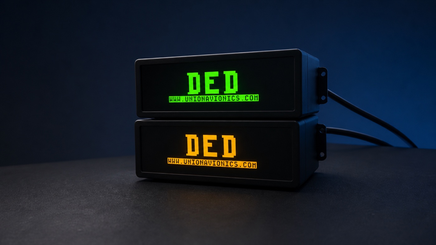
In a complete cockpit, every display has its own position and information role. The value of a DED lies not only in what it shows, but in whether the operator can read it in the expected place and with a familiar visual rhythm.
What does the DED do?
The Data Entry Display works with the ICP panel. After the operator changes a page, selects an item or enters information on the ICP, the DED presents the corresponding page and feedback so that the result can be confirmed immediately.
It normally carries concise character information rather than imagery that demands continuous attention. The operator looks at it when needed, confirms the result and returns attention to the other instruments and outside view.
Operate through the ICP
Select pages, change items and enter information through the ICP panel.
See the current result
The character content changes with system state and provides direct feedback for each action.
Look directly at the DED while using the ICP
Dedicated hardware keeps the DED beside its related controls instead of forcing the user to search for it inside the complete cockpit image on a computer monitor.
Why move it
away from the main display?
A DED window on the primary monitor is sufficient for basic desktop use. In a cockpit-focused project, a dedicated device addresses information position and operating habit instead.
A fixed sight line reduces visual searching. The information no longer moves with software windows or permanently occupies the primary scene, while the distance between hand movement and visual confirmation remains stable.
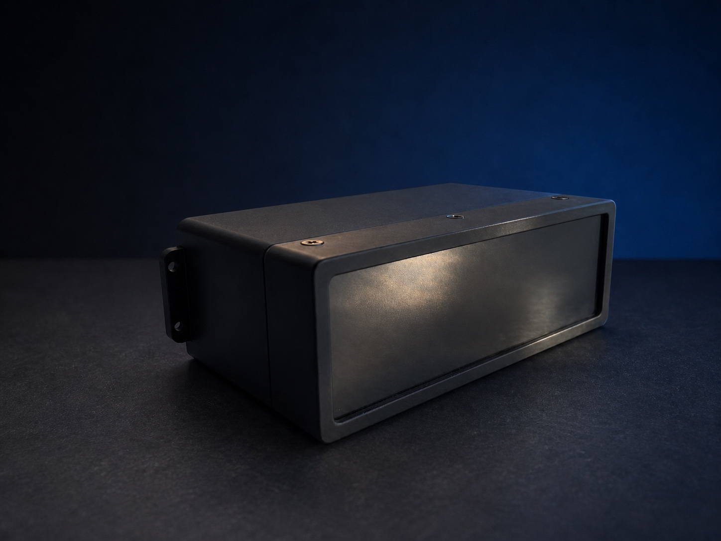
The same content
can read very differently
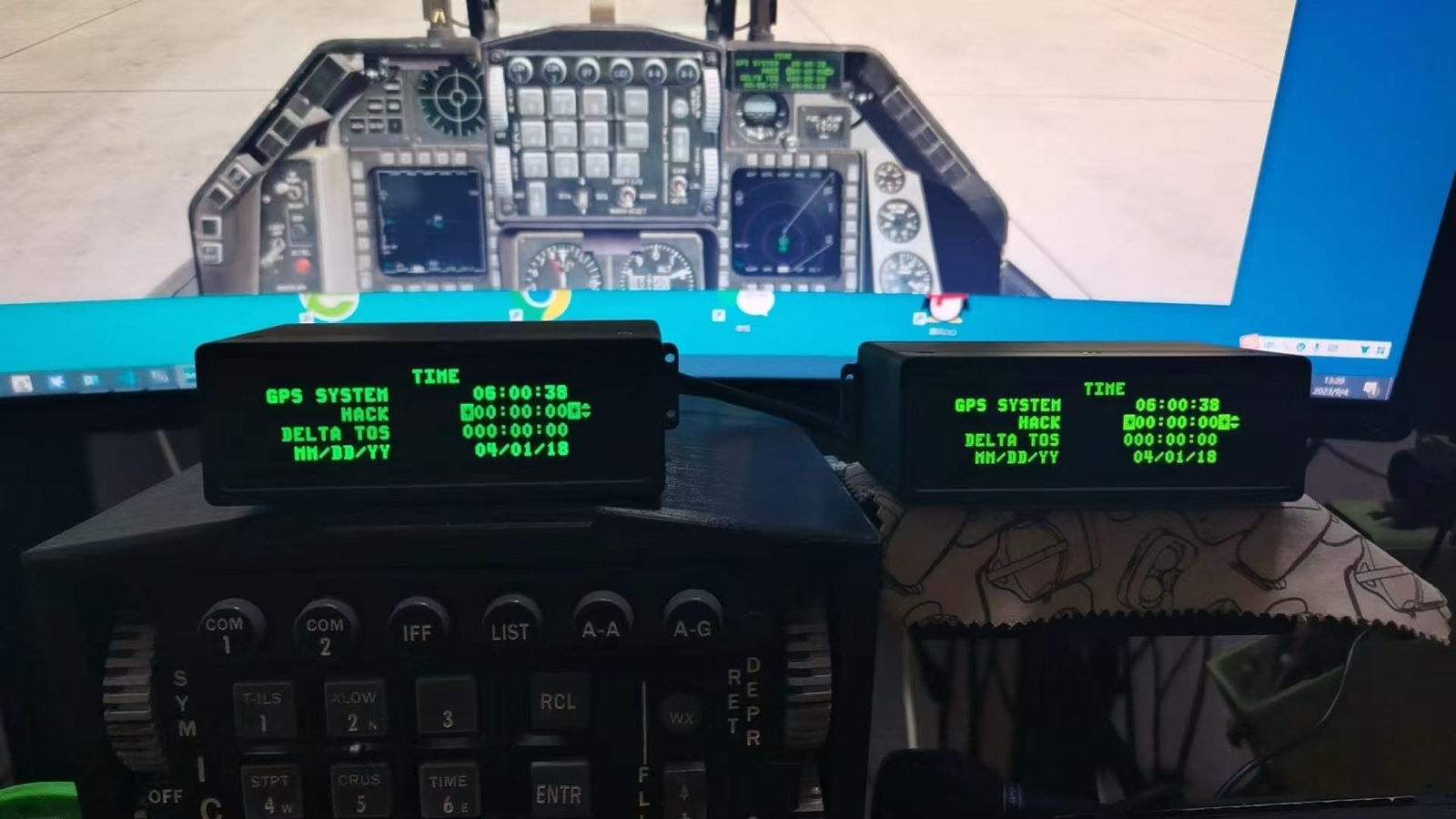
The DED is recognised through character shape, spacing, line spacing, baselines and page whitespace. A single letter may show only a small difference, but those relationships change the reading rhythm when several lines appear together.
Page hierarchy matters as well. Headings, selected items, values and prompts need stable positions so that an experienced user can recognise information by location without reading every character from the beginning.
The original DED uses a 192 × 64 display area, while the practical commercial OLED selected for the product is 256 × 64. The vertical resolution remains the same, but the additional horizontal space changes character positions, margins and page proportions if the original page is merely copied or stretched.
We therefore retain the original dot-matrix character style instead of filling the wider display with a bold substitute. Each page is reconstructed with revised spacing, whitespace and information positions so that the 256 × 64 panel preserves a familiar proportion and reading relationship.
The outline establishes familiarity
Dot-matrix proportions, turns and character width together create the DED visual language.
Character and line spacing affect reading speed
Over-tight spacing causes forms to merge; excessive spacing weakens the connection between related information.
Stable positions build memory
Clear information zones across pages help the operator develop a rapid and repeatable reading habit.
Clear to read,
natural to observe
High contrast does not automatically produce good readability. Excessive brightness can make character edges spread, while insufficient brightness can hide fine strokes. Reflections from the display window further change daytime and night-time viewing.
A DED should be judged through character edges, brightness across the display, oblique viewing and its relationship with neighbouring instruments. Automatic phone-camera exposure can make brightness and contrast differ substantially from what the eye sees, so a single illuminated photograph cannot establish actual display performance.
Defined strokes without bloom
Small characters retain their outline and remain comfortable to read continuously.
Legible across lighting conditions
Brightness supports reading rather than merely making the product look conspicuous when illuminated.
Keep ambient light away from the information
Reflections reduce the effective contrast between characters and background.
Natural beside neighbouring devices
Colour and brightness should be evaluated as part of the full cockpit rather than in isolation.
Extended display and data-driven hardware
are different implementation paths
A dedicated DED is commonly implemented either as an extended computer display or as a data-driven device. Both move the page away from the main monitor, but differ in computer configuration, rendering and device management.
The computer outputs a complete image
The operating system sees another display area and the DED page is placed there through a software window or image extraction.
The device generates the page from data
No additional graphics-card video output is required, and the GPU does not carry another DED image-rendering workload. The computer transmits state and content while the device generates its own characters and pages.
The appropriate path depends on available computer interfaces, software environment, window management and the maintenance approach for the complete cockpit. They are solutions for different integration needs rather than a simple hierarchy.
What to consider
when selecting a DED
Specifications confirm basic suitability, but long-term use depends on whether characters, display, connection and installation work together inside the intended cockpit.
- Characters and pages
Do familiar pages retain natural forms, spacing and information positions?
- Practical readability
Do character edges and page contrast remain stable across brightness levels and viewing angles?
- Reflection and output
Union Avionics uses a custom matte optical film that suppresses ambient reflection without a severe loss of display output, preserving readability in bright environments.
- Connection path
Does the display architecture suit the available computer interfaces and software environment?
- Installation
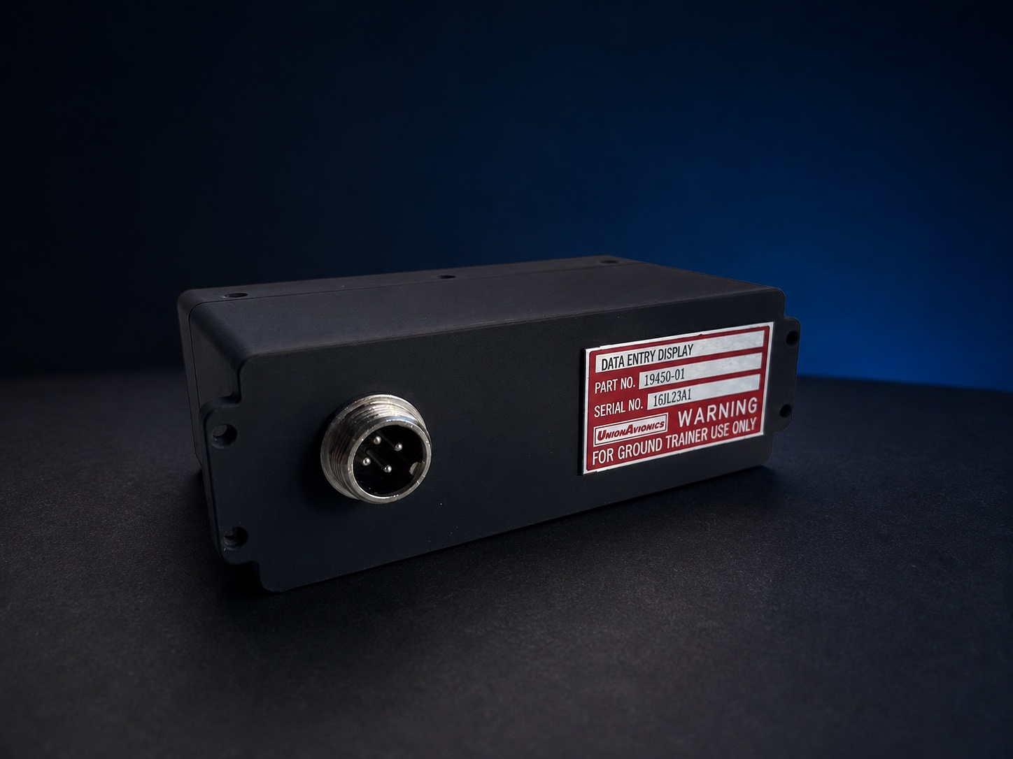
Do the 90.5 mm W × 33 mm H × 53.2 mm D enclosure, four M3 mounting screws, rear clearance and cable path fit the existing cockpit?
- Support
Can the device remain usable as software changes, with clear assistance when required?
A simulator visual style
is not an aviation qualification
A DED can reproduce a particular cockpit character, colour and brightness style, but visual similarity does not demonstrate the environmental, reliability or optical verification required for aircraft equipment.
An NVIS-style appearance is not the same as NVIS compatibility. Compatibility requires appropriate instrumental measurement and validation and cannot be determined by colour seen with the eye or in a photograph.
Union Avionics products are intended only for ground-based simulators and flight simulation. They are not airworthy equipment and are not intended for installation, modification or operation in an aircraft.
These principles
must become a physical product
The Union Avionics DED product page explains the character, display, structure and connection decisions and presents specifications, supported software, installation information and product photography.